Dyson V6 Trigger+ Repair
Planned obsolescence or incompetence?
I repaired this Dyson vacuum for my girlfriend’s mum who would have had to throw it away otherwise.
DC61 Battery Pack
nominal voltage: 21.6 V
rated capacity: 2100 mAh (46 Wh)
6-CELL (214141) 6INR19/66-1
Preliminary Testing
- ✔ PSU 26 VDC at dc barrel plug
- ❌ No current draw when plugged into battery
- Unless the button is pressed no voltage is applied at the terminals
- After pressing the button on top of the battery the light flashes red 32 times and then green once (the 32 flashes of death) before extinguishing and a voltage of 11 VDC was measured at the two battery terminals
Disassembly
After prying the battery casing open using a metal prying tool, plastic spudgers and plastic picks to keep the released latches open the battery measured 22 VDC at the main battery terminals.
Once all latches are opened the smaller part of the shell slides off and the spring loaded plastic button can be removed. To remove the larger part of the casing the light guide (which also acts as a latch) has to be removed.
I had some trouble with this and recommend using a flat head screwdriver to push in the light guide from the outside while shifting the battery cells inside to the other side. Getting the second side loose is the hard part. I resorted to using a plastic prying tool to push out the guide from between the terminals with one side of the guide still in the latch.
Troubleshooting & Repair
Still the battery would not charge when plugged in to the adapter through the dc barrel jack. So I proceeded to check the individual cell voltages.
Cell voltages: (measured 30-12-2023, from most negative to positive)
| Cell number | Cell voltage [V] |
|---|---|
| 1 | 3.807 |
| 2 | 3.481 |
| 3 | 3.94 |
| 4 | 3.93 |
| 5 | 3.89 |
| 6 | 3.914 |
Clearly cell nr. two was significantly lower than the others. After peeling back the hot glue coating I traced the connections from the cells to the ISL94208 battery management chip (BMC). The cells are connected to the BMC via a simple voltage divider with a 1k resistor and varying second resistor values.
According to the datasheet the BMC is capable of not only sensing the cell voltages but can also balance out any differences. How the cells were allowed to become unbalanced is a mystery. The BMC communicates with the onboard microcontroller via I2C so maybe we could spy on them with a serial decoder and find out why it died? After finding tinfever’s DIY firmware for the battery it became clear however, that the feature was intentionally disabled by omitting the required external balancing resistors. Maybe because they tried to implement and test it (there exists a version of the PCB with unpopulated footprints for the required resistors) but failed, but you can surely think of a different reason.
I charged cell nr. two with 4.15 V at 1 A (The power adapter is rated at 750 mA but 1 A should be fine because they were not over discharged) with my bench power supply while watching it like a hawk (wearing safety glasses) and with a closeable metal bin below the table so I could quickly get rid of it in case things got too hot.
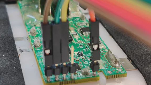
After charging, the second cell voltage is 3.85 V and all cell voltages are similar, according to tinfever’s README they should be within 300 mV of each other. So I proceeded to solder pin headers to the PCB’s exposed THT pads and connected them via a Microchip programmer to my laptop. Uploading the FU-Dyson-BMS software revived the board, many thanks to tinfever.
Battery PCB
The PCB features a micro controller U1 from Microchip and a battery management analog front end IC U2. The output voltage is controlled by a low side switch Q3 which is a n-channel FET.
PCB markings: 18802 - 01/04
BM-IC: Renesas ISL94208 (RZ 743WLQ)
For more hardware info see tinfever’s hardware info section.
Resources
- https://github.com/tinfever/FU-Dyson-BMS (BMS firmware and additional resources)